





News
Contact us and someone will be in touch with you shortly.
Recent News
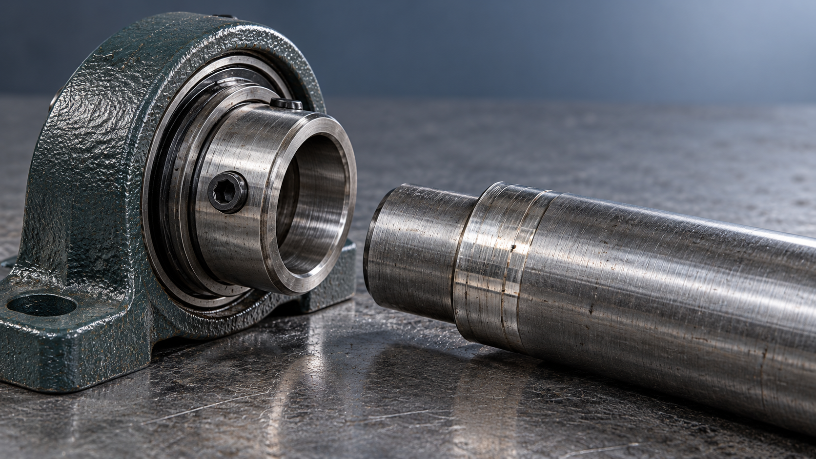
Set screws on insert bearings loosen when their initial clamping force is inadequate, the screw-to-shaft contact settles or wears, or operating forces repeatedly overcome the locking arrangement. Incorrect tightening torque, an undersized shaft, vibration, and repeated starts or reversals are common contributors. Retightening alone leaves the underlying fault in place if the shaft surface is already damaged or the application exceeds the lock’s capacity.
The first distinction is whether the screws are actually rotating backward or remain in position while the inner ring loses its grip. Both produce a “loose bearing,” but they require different repairs. Establishing which movement occurred prevents repeated tightening from turning a recoverable installation problem into permanent shaft damage.
Identify what moved before disturbing the assembly
Stop and isolate the machine, support any load that could move, and let hot components reach a safe inspection temperature. Before turning the screws, record the bearing’s axial position, photograph existing witness marks, and look for relative movement between the shaft and inner ring. A shifted pulley or sprocket does not by itself prove that the bearing lock failed; inspect its attachment separately.
Paint witness marks across the screw and inner ring help reveal screw rotation. Separate marks across the shaft and inner ring reveal loss of shaft grip. Apply these after a verified installation, keeping paint away from seals and contact surfaces. Marks provide evidence of movement; they do not measure retained clamping force.
A screw’s removal torque is not a reliable reconstruction of its installation torque. Corrosion, thread adhesive, contamination, and surface damage change breakaway resistance. Record it if useful, but do not treat a high removal torque as proof that the original assembly was correct.
Installation torque only works with the specified contact conditions
Insufficient torque leaves too little force at the screw tip. Excessive torque creates different problems: stripped threads, a damaged hex socket, screw-tip deformation, or excessive local distortion of the inner ring. A screw that feels exceptionally tight may already be binding in damaged threads rather than pressing firmly against the shaft.
Use the torque specified for the exact insert bearing and locking screw. A generic fastener chart does not account for the inner-ring thread, screw material, point geometry, or permitted ring distortion. Confirm the torque units and use a suitable calibrated tool; a large torque wrench operating near the bottom of its range can make small screws difficult to tighten accurately.
Thread condition matters because tightening torque is divided between friction and useful clamping force. Oil, anti-seize compound, and liquid threadlocker alter that relationship. Follow the bearing manufacturer’s stated assembly condition instead of adding lubricant or adhesive automatically. Where threadlocker is approved, its grade, surface preparation, curing conditions, and compatibility with the prescribed torque all matter.
Seat the bearing and align the assembly before final locking. For designs with multiple set screws, follow the specified tightening sequence and bring every screw to its required torque. Tightening one screw fully while the assembly remains misaligned can establish uneven contact that changes when the housing is subsequently pulled into position.
A worn shaft can defeat correctly tightened screws
Set-screw locking relies on a suitable shaft fit and localized contact between the screw points and shaft. An undersized shaft gives the inner ring more freedom to rock. Each load cycle then works the contact area, gradually enlarging the impressions or wearing the bore. The screws can remain threaded in place while effective grip falls.
Measure the cleaned shaft with a micrometer at several circumferential positions and at more than one axial location within the bearing seat. Compare the results with the shaft tolerance specified for that insert bearing, including any application-specific limits. A single measurement beside the worn track can miss ovality, taper, or a locally reduced diameter.
Inspect the old screw locations closely. Deep craters, raised lips, circumferential grooves, and overlapping impressions reveal different stages of movement. Raised metal around a crater can prevent the inner ring from seating properly during reassembly. Remove only displaced high spots using an appropriate repair method; polishing the entire seat smaller makes a fit problem worse.
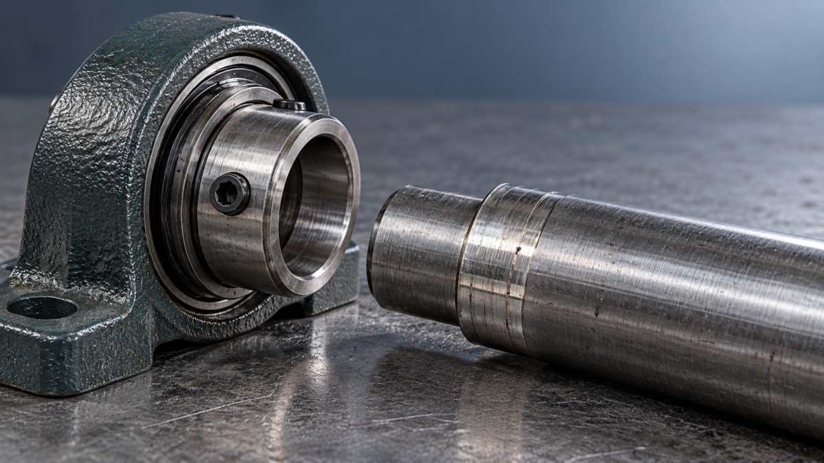
Old screw impressions need careful assessment. A tip landing on the edge of an existing crater can feel tight initially, then settle as the shaft begins to rotate under load. Simply shifting the bearing to create fresh impressions is acceptable only if the new position preserves alignment, support, clearances, and the specified shaft seat. Extensive wear calls for shaft repair or replacement.
Shaft hardness also changes the contact behavior. A very hard surface can limit penetration by a screw point intended to bite into the shaft, while a relatively soft surface can indent and settle under repeated loading. Use the approved screw-point design and shaft requirements together. Drilling dimples or grinding flats without approval changes the contact geometry and can weaken the shaft or complicate future positioning.
Vibration and reversing loads expose a marginal lock
Vibration promotes loosening when it produces relative movement at the threaded joint or screw-to-shaft contact. A general statement that “the machine vibrates” is insufficient to identify the cause. Determine whether the disturbance comes from imbalance, belt excitation, a loose base, coupling misalignment, a damaged bearing, or an external impact process.
Inspect the housing attachment and supporting structure as well as the insert. Loose mounting bolts, a cracked bracket, or uneven support allows the bearing assembly to move even when the screw installation is correct. Tightening the locking screws harder cannot compensate for movement in the machine structure.
Repeated acceleration, braking, and rotation reversal increase the demands on the shaft connection. Drive torque and rotational inertia create transient loads that can exceed those during steady running. A bearing that holds position at constant speed may slip during a jam release or abrupt stop. Relate the first appearance of movement to the operating event instead of relying only on average speed or motor rating.
Axial loads deserve separate attention. Belt or chain misalignment, helical gearing, and process thrust can push the shaft through the inner ring. The bearing’s internal load rating does not establish the axial holding capacity of its set-screw connection. Both limits need to be satisfied, and the locking limit must come from the relevant product data.
Temperature changes and contamination alter the joint
Thermal cycling changes dimensions and redistributes contact forces. The result depends on shaft and ring materials, their temperatures, and the surrounding arrangement. A hot shaft inside a cooler ring behaves differently from an assembly in which both parts warm together. Avoid assuming that every temperature rise either tightens or loosens the connection.
Look for a restrained shaft before blaming thermal expansion alone. If both bearing positions are locked axially and the arrangement provides no intended accommodation for shaft growth, heating can generate axial forces through the bearings and their locks. Correcting this requires review of the locating and expansion arrangement. Loosening one bearing’s set screws as an improvised floating arrangement leaves its shaft retention uncontrolled.
Contamination creates another route to settling. Dirt beneath a screw point, corrosion products on the seat, or debris in the threads can produce an apparently firm assembly that loses contact after startup. Clean the shaft, bore, and screw threads using compatible methods, and inspect for corrosion damage before reassembly. Keep cleaning agents and displaced debris away from bearing seals.
Decide whether the existing locking arrangement remains suitable
Replace screws with damaged points, rounded sockets, or defective threads using the specified replacements. Matching thread diameter and length alone is insufficient: point shape, material, and thread engagement affect performance. Inspect the tapped holes too. A new screw cannot restore stripped or cracked inner-ring threads.
Where the shaft and installation are sound but movement recurs under verified operating loads, review the locking method. Eccentric collars, concentric clamping arrangements, and adapter-mounted designs have different shaft requirements, installation procedures, and operating limitations. An eccentric collar, for example, requires attention to its prescribed locking direction and suitability for reversing duty. A different lock should be selected against the actual load cycle and available shaft geometry.
Keep replacement specifications tied to the bearing construction. A double-row cylindrical roller bearing such as NNU41/1000K30/W33 uses a different mounting arrangement; its installation data cannot establish tightening torque or shaft retention capacity for set-screw insert bearings.
Make the restart prove the repair
Reassembly should follow a documented correction: restored shaft fit, renewed locking components, corrected alignment, reduced structural movement, or a suitably selected locking design. Record the shaft measurements, bearing identification, screw specification, assembly condition, and applied torque. These details make any recurrence easier to distinguish from the original fault.
After reassembly, confirm free rotation where the machine design permits, restore guards, and run a controlled trial under the applicable startup procedure. Include the operating event associated with the previous failure, such as warming to normal temperature or a permitted reversal. Observe vibration, temperature trends, and shaft position without approaching rotating parts.
Stop and isolate the machine before examining the witness marks. Any new screw rotation or shaft-to-ring displacement means the repair has not held. Follow the manufacturer’s instructions for any initial settling inspection or retorque; repeated tightening at arbitrary intervals can conceal progressive shaft damage and overstress the screws.


Huamai Power
Thank you very much for writing to us. Please leave your message and contact information, we will reply to you within 24 hours.