





News
Contact us and someone will be in touch with you shortly.
Recent News
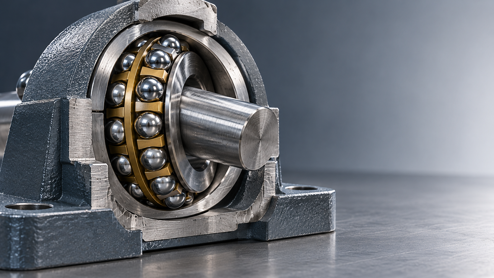
How much shaft misalignment can self-aligning ball bearings handle?
Many open Self-aligning Ball Bearings can accommodate approximately 2–3° of angular misalignment, but that range is a starting point, not a universal specification. The permissible angle depends on the bearing design, sealing arrangement, available internal clearance and operating conditions. The exact manufacturer’s catalog must govern the selection.
The distinction matters when evaluating a flexible shaft, imperfectly aligned housings or a replacement bearing. A catalog limit is not an operating target, and angular compensation does not directly correct parallel shaft offset. The useful question is therefore not simply “How many degrees?” but “How much movement can this bearing accommodate in this assembly, under this load, throughout its duty cycle?”
What the allowable angle actually describes
A self-aligning ball bearing has two rows of balls and a common spherical raceway in the outer ring. This geometry allows the inner ring, balls and cage to tilt relative to the outer ring. It can therefore accommodate a difference between the shaft’s local axis and the housing bore axis without the same sensitivity to edge loading associated with many rigid bearing arrangements.
The specified angle describes this relative angular displacement between the rings. It does not mean that every part surrounding the bearing can tolerate the same movement. Shaft shoulders, housing covers, grease passages, external seals and adjacent components may restrict the usable angle before the bearing reaches its internal geometric limit.
Three conditions should be kept separate:
- Angular misalignment: the shaft and housing axes meet at an angle. This is the condition the bearing is designed to accommodate.
- Parallel offset: two axes are displaced sideways while remaining parallel. Self-alignment does not translate the shaft to eliminate that offset.
- Shaft deflection: the shaft bends under load, creating a local slope at each bearing. Those local slopes, rather than the maximum bend alone, determine the required angular accommodation.
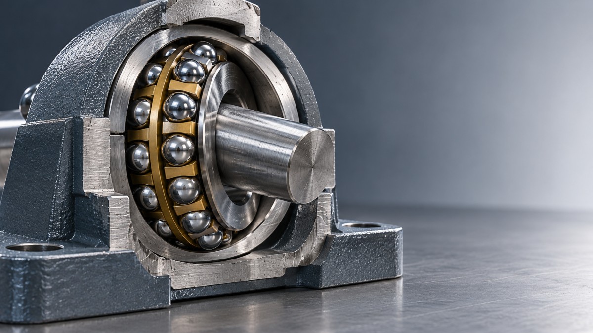
Offset bearing supports can force a shaft into a tilted or bent condition. Self-aligning bearings may accommodate the resulting local angles, but they do not remove the underlying dimensional error or its effects on couplings, gears and seals.
Why the same nominal angle does not suit every application
Open designs generally offer more angular freedom than sealed versions. An integrated seal can limit tilt because its lip must remain correctly positioned against its running surface. Do not transfer the permissible angle from an open bearing to a sealed bearing with similar dimensions. Check the full designation, including suffixes.
Internal clearance also needs careful interpretation. Mounting interference and temperature differences between the rings change operating clearance. Excessively reduced clearance can produce heat and undesirable internal loading. However, choosing a larger clearance class is not a reliable way to increase the rated misalignment angle; that angle remains a design-specific characteristic.
Load and speed introduce further constraints. A bearing that can geometrically tilt through a stated angle still needs adequate fatigue life, lubrication and thermal stability at the operating point. Combined radial and axial loading must be checked using the manufacturer’s calculation method. A permissible angle alone cannot establish suitability.
There is also a difference between a steady angular position and continuously changing misalignment. A shaft that settles into a stable deflected shape is not equivalent to an assembly whose housing moves, vibrates or repeatedly changes angle. Ask whether the published limit applies to the actual motion involved, especially when the angle changes rapidly or operation approaches the stated limit.
Turn shaft and housing measurements into a usable requirement
Start with the operating geometry rather than the bearing catalog. Determine the housing bore directions, shaft support locations and expected shaft deflection under load. For a straight shaft between supports, a small angular difference can be estimated from:
θ = arctan(Δ/L)
Here, Δ is the transverse displacement and L is the corresponding axial distance. As a purely geometric example, a 1 mm displacement over 500 mm gives approximately 0.115°. This calculation describes an overall slope; it does not establish the local bearing angle for a shaft that bends appreciably.
For a flexible shaft, use the slope at each bearing location from a suitable beam calculation or structural model. Include the housing axis direction at that location. The relevant misalignment is the difference between those directions, not simply the slope measured against the machine frame.
The operating requirement should also account for assembly tolerances, housing deformation, thermal movement and credible transient loads. These contributions have direction as well as magnitude. Adding every maximum arithmetically may be unnecessarily conservative, while ignoring an unfavorable combination can understate the requirement. Document the assumptions.
Keep a justified margin below the confirmed permissible angle. There is no single percentage suitable for every installation: a steady, well-characterized duty and an impact-loaded machine with uncertain frame movement need different allowances. If the selection works only when every tolerance is favorable, revisit the arrangement.
Choose the bearing type around the load, not just the angle
Self-aligning ball bearings are useful where angular accommodation is required alongside relatively low friction and predominantly radial loading. They are not automatically the right choice for heavy loads, substantial thrust or tightly controlled shaft positioning.
Compactness can obscure an important difference during cross-referencing. A designation such as K15X21X15 is commonly associated with a needle roller and cage assembly, not a self-aligning ball bearing. Confirm the supplier’s drawing and construction before comparing it with a self-aligning design. A small radial envelope does not imply equivalent misalignment capability, and raceway requirements may be entirely different.
Likewise, a spherical outer surface on an insert bearing does not make it identical to a self-aligning ball bearing. The adjustment mechanism, housing interface and permissible movement during operation differ. Compare complete arrangements rather than relying on the word “self-aligning” in a description.
Check the assembly before approving the selection
A bearing can pass the angular check and still fail the installation review. A frequent concern is axial restraint: thermal shaft growth needs a defined path. Self-alignment provides angular freedom, not automatic axial displacement. Establish which support locates the shaft and how the other support accommodates expansion.
For tapered-bore versions, mounting changes internal clearance. Follow the applicable supplier procedure for drive-up or clearance reduction rather than tightening until the assembly merely feels secure. For cylindrical-bore versions, verify shaft and housing fits against load direction and operating temperature.
External seals deserve their own review. The bearing may tolerate the shaft angle while a nearby lip seal experiences uneven contact or leakage. Check the actual shaft position at the seal location, including runout and deflection. Lubrication access and contamination protection must remain effective throughout the expected movement.
Commissioning should then test the assumptions through representative operating conditions. Monitor temperature, vibration, noise and leakage, and compare them with the equipment’s acceptance criteria. These observations support validation; they do not replace the initial load and life calculations.
What to request from the bearing supplier
A useful technical enquiry includes the full designation, radial and axial loads, speed range, duty cycle, calculated angular movement, fits, temperatures, lubrication method and surrounding assembly drawing. Ask for the permissible angle for that exact variant and the conditions attached to it—not a general statement about the bearing family.
Shandong Huamai Power Technology Co., Ltd., based in Linqing, Liaocheng, Shandong Province, combines bearing R&D, design, precision manufacturing and technical services. Its broader portfolio includes deep groove ball, spherical roller, tapered roller, cylindrical roller, thrust and angular contact bearings, alongside non-standard development. That breadth is relevant when the evaluation points toward a different bearing type or a revised mounting arrangement rather than a direct replacement.
For a customized solution, agree which dimensions, operating conditions and acceptance criteria require confirmation. Special dimensions alone do not establish load capacity, life or angular capability; those characteristics need supporting engineering documentation.
Use approximately 2–3° only as an initial screening range for many open designs. Approve the bearing only after its exact permissible angle exceeds the calculated operating requirement with a justified margin, and the load, speed, clearance, sealing and axial-location checks also pass. If angular capacity is the only parameter confirmed, the selection is not yet complete.


Huamai Power
Thank you very much for writing to us. Please leave your message and contact information, we will reply to you within 24 hours.