





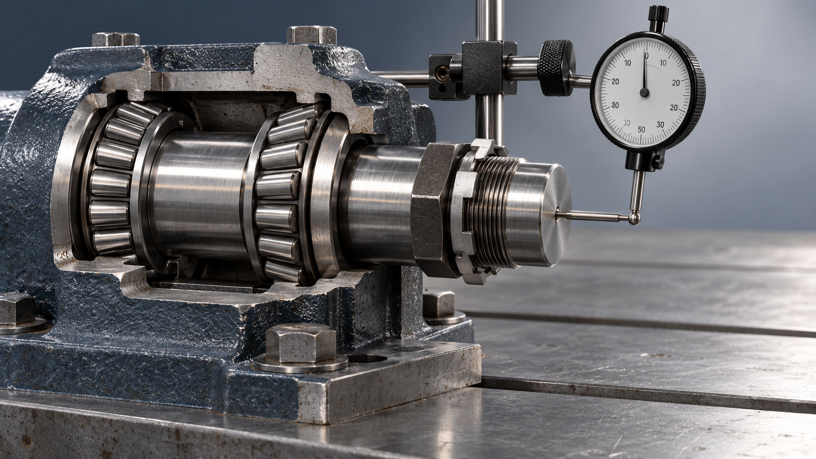
Set endplay by seating the bearings, measuring axial movement with a dial indicator, and adjusting until the secured assembly meets the equipment manufacturer’s specified clearance.
Correct adjustment helps maintenance technicians prevent overheating, excessive shaft movement, and premature failure. Tightening an adjusting nut by feel cannot reliably establish the required setting.
This guide explains how to prepare the assembly, measure movement, make controlled adjustments, and verify the result after locking the nut or securing the cover.
Before starting, confirm whether your application requires measurable endplay, preload, or a factory preset assembly. These arrangements require different procedures and cannot share one adjustment rule.
What Endplay Should You Set Before Returning Equipment to Service?
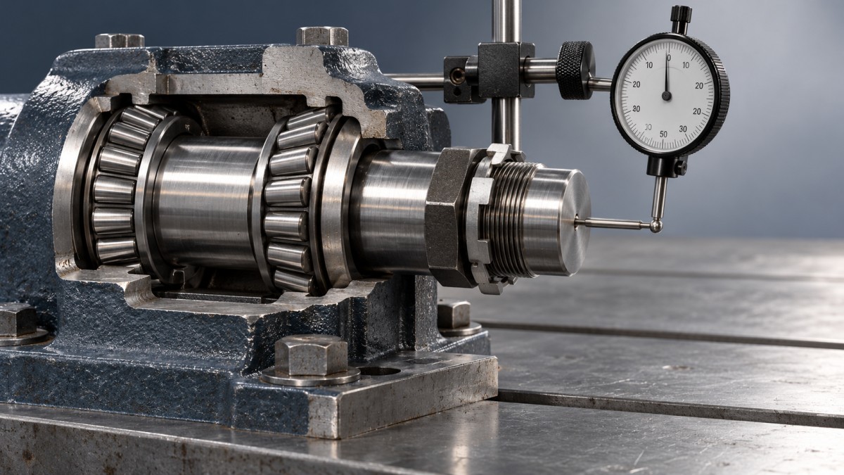
The correct target comes from the equipment service manual or an approved engineering specification. There is no universal endplay value for all tapered roller bearings.
Endplay is the axial movement available between opposing thrust limits. In an adjustable bearing arrangement, it reflects clearance across the assembled system under specified measurement conditions.
Too much clearance can allow shaft movement, gear misalignment, vibration, or seal problems. Too little clearance can create unintended preload and increase operating temperature substantially.
Some applications deliberately use preload to improve stiffness or positioning. If preload is specified, an endplay measurement alone cannot confirm that the required setting exists.
Do not copy a clearance value from another machine simply because its bearing looks similar. Housing materials, shaft dimensions, speed, lubrication, and operating temperature influence requirements.
If the specification is missing, identify the machine, bearing arrangement, and component references before proceeding. Ask the equipment manufacturer or qualified application engineer for guidance.
Identify the Adjustment Method Before Touching the Nut
Most service procedures address an opposed pair of tapered roller bearings supporting a shaft or hub. An individual bearing normally cannot locate the shaft in both directions.
Adjustment may use a threaded nut, shims behind an end cover, a spacer arrangement, or a cartridge assembly. Determine which component actually controls axial clearance.
A threaded adjuster changes the axial position of a bearing ring. Shim adjustments change a locating surface, while precision spacers establish spacing within a controlled stack.
For spacer systems, confirm whether spacers are reusable, selectively matched, ground to size, or designed to collapse during assembly. Their service requirements can differ significantly.
Do not loosen a retaining nut to create clearance in a design requiring a fully clamped spacer stack. That can compromise retention without establishing proper internal geometry.
Also identify how the setting is locked. Cotter pins, tab washers, locknuts, and cover bolts can each affect the final position or measured axial movement.
Prepare the Bearings and Tools for a Reliable Measurement
Use a dial indicator with resolution suitable for the specified tolerance, a rigid mounting fixture, the correct adjustment tools, and a calibrated torque wrench where required.
Obtain the service procedure, including its measurement temperature, lubrication condition, seating method, and locking instructions. Check whether seals or other components must already be installed.
Support the machine securely and isolate hazardous energy before accessing the assembly. Remove loads or connections that would prevent controlled axial movement during the measurement.
Inspect bearing raceways, rollers, cages, shoulders, and locating surfaces. Replace damaged components according to the approved repair procedure; adjustment cannot restore pitted or distorted raceways.
Clean mating faces and remove burrs that prevent full seating. Dirt trapped behind a cup or cone can produce a misleading setting that changes during operation.
Confirm that the cup and cone belong to an approved combination. Similar dimensions do not establish interchangeability, particularly when replacing components from different bearing series.
Apply the specified assembly lubricant and install components using appropriate tooling. Transfer mounting force through the ring being fitted, avoiding force transmission through the rolling elements.
Check that the rings contact their shoulders fully. A bearing stopped short by interference, contamination, or a damaged shoulder can settle later and alter endplay.
Seat the Rollers Before Making the Final Adjustment
Initial seating brings rollers into consistent contact with the raceways and guiding flange. Without this step, a clearance reading may change after the first rotation.
Follow the manufacturer’s seating sequence, which may involve rotating the shaft or hub while applying a specified temporary tightening torque or another controlled axial load.
Rotate as directed so the rollers settle into position. Tightening a stationary assembly can leave the rollers inconsistently seated and make the apparent adjustment unreliable.
Distinguish the temporary seating torque from the final adjustment or retention requirement. A torque used during seating does not automatically represent the correct running setting.
After seating, release or readjust the assembly exactly as instructed. Avoid a generic instruction such as “back off one flat” unless the service procedure specifies it.
If rotation feels rough, catches repeatedly, or requires unexpected force, investigate before continuing. Contamination, component damage, incorrect fits, or assembly errors may be responsible for resistance.
Measure Endplay with a Dial Indicator
The indicator must measure movement between the rotating member and its stationary support. Mount its base rigidly on the housing or another suitable reference surface.
For a hub rotating on a stationary spindle, use a fixture referenced to the spindle or support. Follow the equipment procedure for the indicator arrangement.
Place the contact tip against a clean, flat surface on the moving component, with the plunger aligned as closely as practical to the shaft axis.
Give the indicator sufficient travel in both directions and check that the stand cannot shift. Angled contact or bracket flex can distort a small clearance reading.
- Move the shaft or hub gently to one axial limit using the specified checking force.
- Hold it consistently at that limit and zero the indicator.
- Move it to the opposite limit without rocking or rotating the assembly unnecessarily.
- Record the total indicator movement, then repeat the check to confirm consistency.
Apply force along the axis. Rocking a hub at its rim can combine angular movement with axial displacement, producing a reading that overstates actual endplay.
Use the checking force specified by the manufacturer when available. Excessive force can deflect components, while insufficient force may fail to overcome seal drag or friction.
Repeat the measurement after rotating the assembly to reseat the rollers. Readings should remain consistent enough to distinguish actual clearance from movement in the fixture.
A zero reading does not prove correct preload. It may indicate preload, insufficient checking force, restricted movement, or an indicator setup that cannot detect axial displacement.
Adjust Gradually and Recheck After Locking
For a threaded adjustment, move the nut in small increments according to the service procedure. Rotate or reseat the assembly as required before measuring again.
Thread pitch converts small angular changes into axial movement. This makes rough estimates unreliable when the acceptable clearance band is narrow or the locking positions are widely spaced.
For shimmed covers, establish whether adding shims increases or decreases clearance in that specific design. The direction depends on which component the cover or retainer locates.
Measure shims and keep mating surfaces clean. Tighten cover bolts in the specified sequence and to the required torque before judging the resulting axial movement.
For illustration only, suppose an approved service specification requires 0.03–0.08 mm endplay. A repeatable reading of 0.06 mm falls within that example range before locking.
After securing the lock, measure again. If the reading changes to 0.02 mm, the assembly fails that example requirement even though the earlier measurement was acceptable.
These numbers demonstrate the checking process only; they are not recommended settings for your equipment. Use the actual specification and its stated measurement conditions throughout.
Engage the locking device exactly as instructed. If the target cannot be achieved at an available locking position, follow the approved correction procedure for that arrangement.
Finally, repeat the axial movement check with all adjustment components secured. Record the final locked reading, because this is the condition being returned to service.
What Should You Check When the Reading Will Not Stabilize?
Unstable measurements usually require investigation before further adjustment. Repeatedly changing the nut position can hide the underlying problem and leave the assembly incorrectly set after operation.
If seal drag makes movement difficult to detect, consult the specified measurement procedure. Do not remove required seals or compensate with uncontrolled force merely to obtain movement.
Continued inconsistency can also indicate wear outside the bearing itself. Inspect shaft shoulders, housing seats, retainers, and threads for movement that the indicator may be capturing.
Verify Operation and Keep a Useful Service Record
Cold installation endplay and operating clearance are related but not identical. Temperature differences between the shaft and housing can change the setting as equipment warms.
This is why the specified installation condition matters. Do not tighten an assembly further simply because measurable clearance feels undesirable while the equipment is cold.
Restore lubrication and complete all required assembly checks before startup. Run the equipment according to its commissioning procedure while monitoring temperature, noise, vibration, and leakage.
Unexpected heating requires investigation of adjustment, lubrication, seals, fits, and loading. Temperature alone cannot identify the cause, and tightening the assembly may make the problem worse.
When sourcing replacements, provide the bearing reference, arrangement, and operating conditions. A catalog item such as FC90114300 requires application confirmation before selection or installation.
Shandong Huamai Power Technology Co., Ltd. manufactures standard and customized bearings. For technical inquiries, include drawings and service requirements so suitability can be assessed against the application.
Record the final locked endplay, specification source, measurement conditions, and replaced components. This gives the next technician a practical baseline for troubleshooting and future maintenance.
Reliable Endplay Starts with the Specification and Ends with Verification
To set tapered roller bearings correctly, confirm the required arrangement, seat the components, measure axial movement, and adjust using the procedure approved for that machine.
Accept the assembly only after the locked setting meets specification and required operating checks are complete. Consistent measurement and accurate records make future maintenance more dependable.

