





News
Contact us and someone will be in touch with you shortly.
Recent News
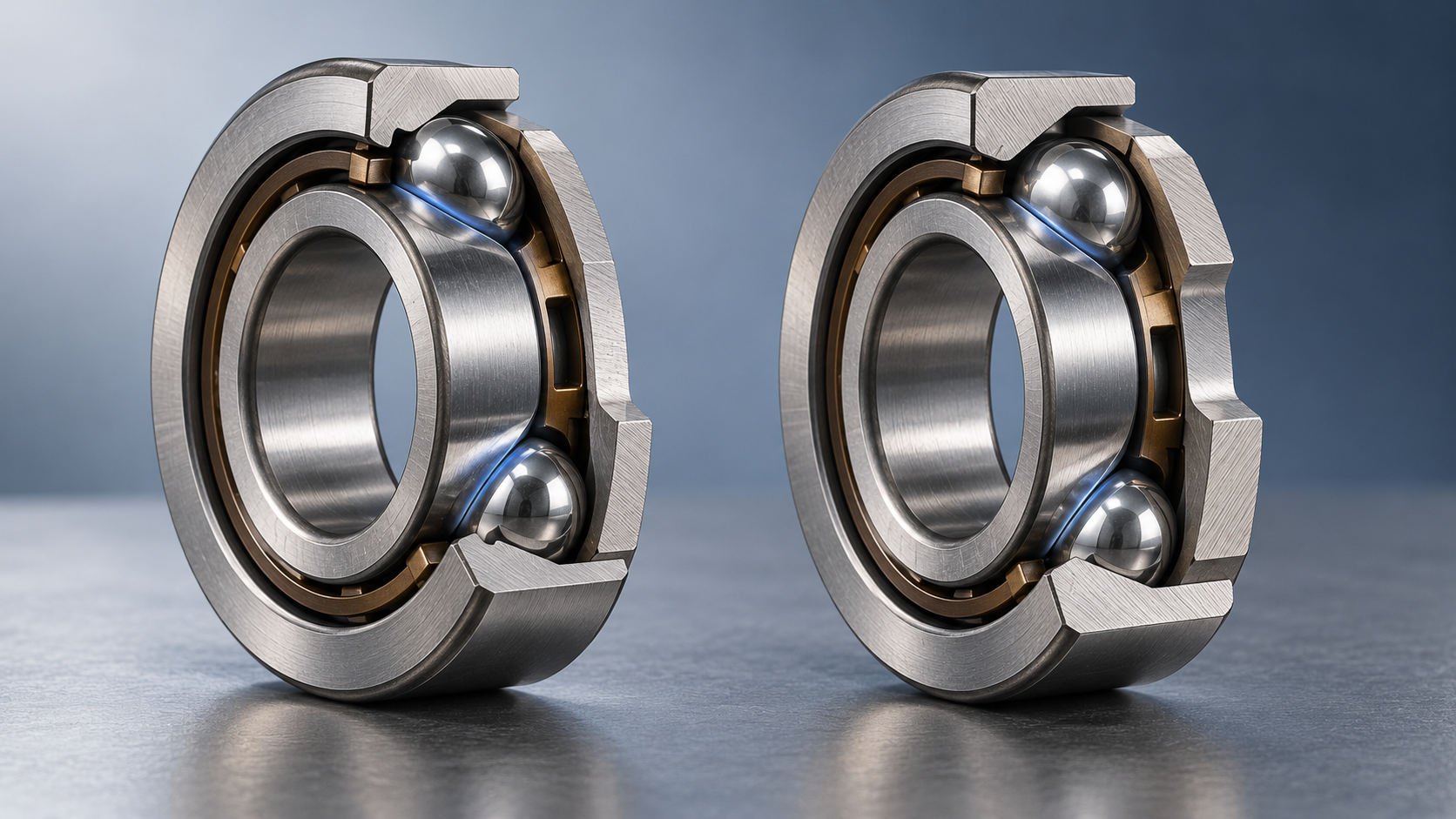
How contact angle affects axial load capacity in angular contact ball bearings
Why can two similarly sized Angular Contact Ball Bearings support different axial loads? Contact angle is a key factor: a larger angle generally improves axial load capability, but also changes stiffness, speed suitability, and behavior under combined loading. For a meaningful comparison, the nominal angle must be considered alongside internal geometry, preload, bearing arrangement, and operating conditions.
That distinction matters in practical selection. A bearing suitable for a heavily loaded, moderate-speed shaft may be a poor choice for a high-speed spindle, even when both applications use the same bore diameter. The useful question is not simply “Which angle carries more thrust?” It is “Which bearing arrangement carries the actual load spectrum without unacceptable heat, deflection, or fatigue?”
Contact angle determines how force travels through the bearing
The contact angle is the angle between the line of action through the ball–raceway contacts and a plane perpendicular to the bearing axis. At a small angle, the contact force acts mainly in the radial direction. As the angle increases, a greater proportion of that force acts axially.
For a simplified contact-force model, the axial component is Q sin α and the radial component is Q cos α, where Q is the normal contact force and α is the contact angle. This explains the basic advantage of a larger angle: more axial force can be transmitted for the same contact-force magnitude.
For illustration, sin 15° is approximately 0.259, while sin 40° is approximately 0.643. The axial component of an equal contact force is therefore about 2.5 times greater at 40°. That does not mean a 40° bearing has 2.5 times the permissible axial load of a 15° bearing. Actual capacity depends on how loads are distributed among the balls, contact stresses, raceway geometry, and operating limits.
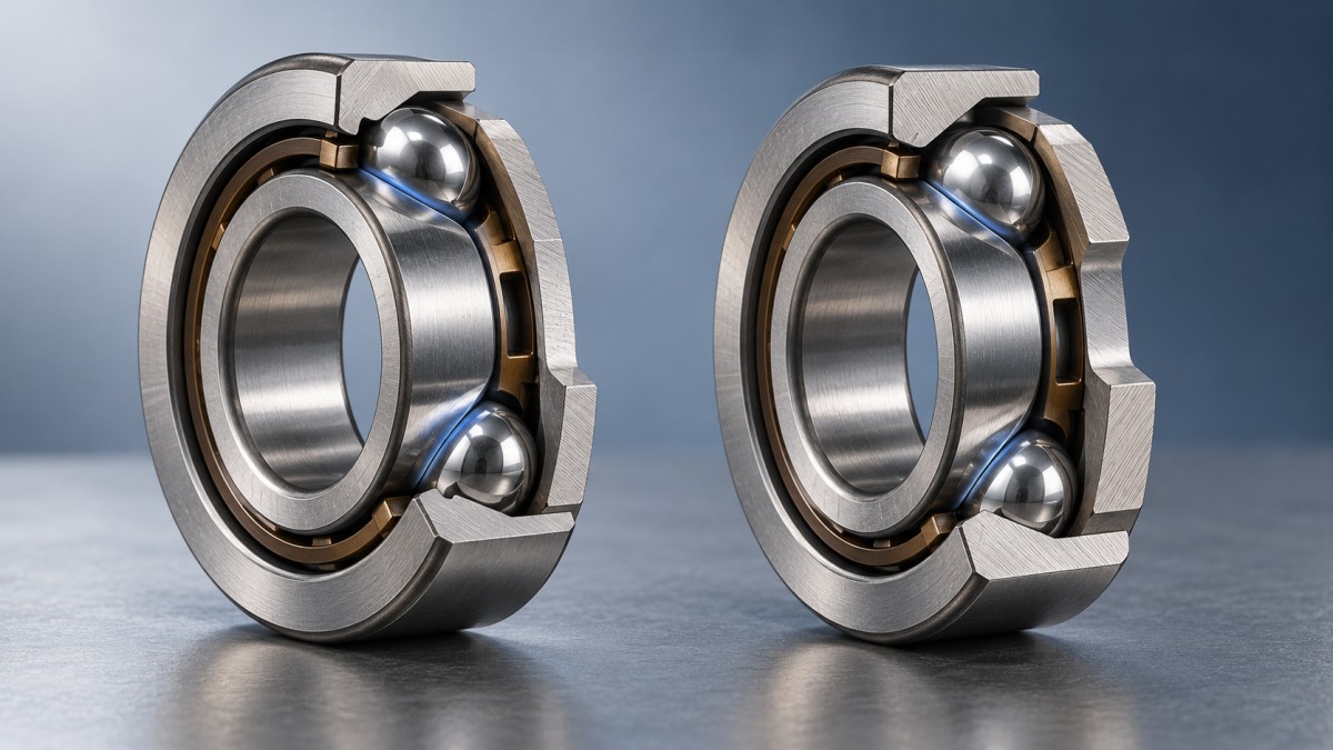
A cross-sectional comparison is especially useful here: the steeper contact line makes the axial load path easier to understand. It also shows why a conventional single-row angular contact bearing supports axial load primarily in one direction. Reversing thrust normally requires an opposed bearing or another suitable arrangement.
Why nominal angle is not an axial load rating
Common catalog contact angles include 15°, 25°, and 40°, although available angles and designation conventions vary by manufacturer and product family. Lower angles are frequently used where high-speed performance is important. Larger angles are often considered when thrust load and axial rigidity dominate. These are selection tendencies, not universal operating rules.
Two bearings with identical external dimensions and nominal contact angles can still have different ratings. Ball diameter and count, raceway conformity, ring geometry, materials, and manufacturing quality influence their performance. Cage design and lubrication affect the operating envelope as well. The angle describes the load path; it does not describe the entire bearing.
When reviewing a candidate such as 7020AC, confirm the contact-angle designation in the supplier’s documentation rather than transferring assumptions from another brand’s suffix system. The dimensional designation alone does not establish preload, permissible speed, matched-pair characteristics, or allowable thrust.
Also distinguish the basic dynamic load rating C from a permissible axial load. C is a reference rating used in fatigue-life calculations, not a direct thrust limit. The basic static load rating C0 addresses a different criterion involving permanent deformation at heavily loaded contacts. Neither should be treated as an unrestricted operating load.
Combined loads: where the simple comparison breaks down
Most shafts do not apply pure thrust. A machine-tool spindle sees cutting forces and moments; a motor shaft may experience radial belt pull alongside axial process loads. Under these conditions, the radial load changes the distribution of ball loads, and an angular contact bearing also develops an induced axial force that must be reacted elsewhere in the arrangement.
For many catalog calculations, the equivalent dynamic bearing load takes the form P = XFr + YFa. However, the applicable equation, threshold conditions, and X and Y factors depend on bearing design, contact angle, and arrangement. They must come from the relevant manufacturer’s calculation method. Using factors from a different bearing series can invalidate an otherwise careful life calculation.
ISO 281 provides the framework for calculating dynamic load ratings and rating life. For ball bearings, the basic rating-life relationship uses a load exponent of 3, making the result sensitive to equivalent load. ISO 76 addresses static load ratings. These standards do not replace application checks for speed, lubrication, temperature, or arrangement-specific load distribution.
In a reversing-load application, calculate the relevant operating cases separately. A brief peak thrust may govern static safety or displacement, while sustained combined loading governs fatigue life. Averaging those conditions into one convenient force can hide the condition that actually limits the design.
Preload improves rigidity, but consumes operating margin
A larger contact angle generally favors axial stiffness, all else being comparable. Yet stiffness is not the same as load capacity. Stiffness describes resistance to displacement; capacity concerns acceptable stress, life, and operating limits. A preloaded assembly can feel very rigid while carrying substantial internal load before any external thrust is applied.
Preload removes clearance and establishes contact conditions that improve positioning and running behavior. In an opposed pair, external axial load increases loading on one bearing and reduces it on the other. With sufficient thrust, the opposing bearing may become unloaded. Beyond that point, assembly stiffness and rolling behavior can change significantly.
More preload is therefore not a substitute for choosing the correct contact angle. Excessive preload increases friction and heat, and thermal expansion can further alter the internal load. Depending on the shaft, housing, materials, and arrangement, operating preload may rise or fall as the assembly warms.
The operating contact angle can also differ from the nominal angle because of elastic deformation and high-speed effects. For precision spindle work, room-temperature catalog geometry is only the starting point. The warm, rotating assembly is the condition that must meet the displacement and temperature requirements.
Bearing arrangement can matter as much as angle
A contact-angle decision made without an arrangement drawing is incomplete. The same bearing design behaves differently depending on how it is paired, spaced, supported, and preloaded.
- Back-to-back arrangements: provide axial support in both directions and a wider effective support spread, generally favoring resistance to overturning moments.
- Face-to-face arrangements: also support axial loads in both directions, with a narrower effective support spread and generally less moment rigidity than an otherwise comparable back-to-back pair.
- Tandem arrangements: allow suitably matched bearings to share axial load in one direction. Reverse thrust still requires an opposing support.
A tandem pair should not be assigned twice the single-bearing capacity without checking the manufacturer’s combination factors and matching requirements. Load sharing depends on dimensional accuracy, mounting conditions, and elastic deflection. Likewise, neither an opposed pair nor a tandem set compensates for poor shoulder squareness or distorted housing seats.
The speed trade-off needs an application-level check
For otherwise comparable designs, a smaller contact angle is often favored at high speed because contact kinematics and frictional behavior differ with angle. However, there is no reliable universal percentage by which speed must decrease when angle increases. Cage guidance, ball material, preload, lubrication method, and heat removal can change the result substantially.
Consider two design priorities. A high-speed finishing spindle may tolerate modest thrust but demand low temperature rise and stable tool position. A slower shaft subjected to sustained process thrust may justify a larger angle. Selecting the larger angle for both simply because it offers stronger axial support misses the first application’s principal constraint.
Check whether a published speed value is a reference speed or a limiting speed, and identify the lubrication and preload conditions behind it. Grease and oil-air arrangements are not interchangeable assumptions. Low external load also deserves attention: insufficient loading can promote skidding, particularly at high speed. Minimum-load guidance belongs in the review alongside maximum-load checks.
What to request before approving the bearing
A useful technical submission should connect the proposed bearing to the shaft’s actual duty. Request the following information where applicable:
- Radial and axial load cases, including thrust direction, peaks, moments, and duty duration.
- Confirmed contact angle, dynamic and static ratings, and the calculation factors for the proposed arrangement.
- Preload specification, matching requirements, and expected thermal effects on internal loading.
- Speed limits with stated lubrication conditions, plus minimum-load requirements.
- Fits, shoulder requirements, mounting tolerances, and allowable shaft displacement.
Shandong Huamai Power Technology Co., Ltd., based in Linqing, Liaocheng, Shandong Province, combines bearing R&D, design, precision manufacturing, sales, and technical services. Its portfolio includes angular contact bearings and other standard bearing types, alongside customized non-standard designs. For an application review, that range is useful only when the operating requirements are clearly defined: a standard bearing should be assessed before special dimensions or internal modifications are introduced.
If axial load is the limiting factor, increasing contact angle is a reasonable option to investigate—not an automatic approval. Confirm life, static safety, thermal behavior, stiffness, and load reversal with the intended arrangement. If the comparison rests only on bore size and nominal angle, it is not yet a complete bearing selection.


Huamai Power
Thank you very much for writing to us. Please leave your message and contact information, we will reply to you within 24 hours.